

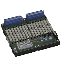
Termination Board HiCTB16-TRI-DIISS-EL-PL-Y1
- System board for Schneider Electric, Tricon series by Triconex
- For 32-channel (16+16) DI cards 3503E and 3505E
- For 16 modules
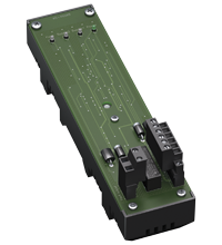
- Recommended module: HiC2851 (DI)
- 24 V DC supply
- Hazardous area: pluggable screw terminals, blue
- Non-hazardous area: ELCO socket, 56-pin


Please note: All product-related documents, such as certificates, declarations of conformity, etc., which were issued prior to the conversion under the name Pepperl+Fuchs GmbH or Pepperl+Fuchs AG, also apply to Pepperl+Fuchs SE.
Datasheet excerpt: Technical data of HiCTB16-TRI-DIISS-EL-PL-Y1
| Supply | ||
|---|---|---|
| Connection | X20: terminals 3, 5(+); 4, 6(-) | |
| Nominal voltage | 24 V DC , in consideration of rated voltage of used isolators | |
| Voltage drop | 0.9 V , voltage drop across the series diode on the termination board must be considered | |
| Ripple | ≤ 10 % | |
| Fusing | 4 A , in each case for 16 modules | |
| Power dissipation | ≤ 500 mW , without modules | |
| Reverse polarity protection | yes | |
| Redundancy | ||
| Supply | Redundancy available. The supply for the isolators is decoupled, monitored and fused. | |
| Fault indication output | ||
| Connection | fault bus (Fault) : X20: terminals 1, 2 |
|
| Output type | volt-free contact | |
| Switch behaviour | fault bus (Fault) - no fault: relay contact of the fault indication board closed - power supply fault: relay contact of the fault indication board open - module fault: relay contact of the fault indication board open |
|
| Contact loading | fault bus (Fault) : 30 V DC , 1 A , see fault indication board | |
| Indicators/settings | ||
| Display elements | LED PWR1 (termination board power supply), green LED LED PWR2 (termination board power supply), green LED |
|
| Directive conformity | ||
| Electromagnetic compatibility | ||
| Directive 2014/30/EU | EN 61326-1:2013 (industrial locations) | |
| Conformity | ||
| Electromagnetic compatibility | NE 21:2017 For further information see system description. |
|
| Degree of protection | IEC 60529:2001 | |
| Ambient conditions | ||
| Ambient temperature | -20 ... 60 °C (-4 ... 140 °F) | |
| Storage temperature | -40 ... 70 °C (-40 ... 158 °F) | |
| Mechanical specifications | ||
| Degree of protection | IP20 | |
| Connection | ||
| Field side | explosion hazardous area: pluggable screw terminals , blue | |
| Control side | non-explosion hazardous area: ELCO socket, 56-pin | |
| Supply | pluggable screw terminals , black | |
| Fault output | pluggable screw terminals , black | |
| Core cross section | screw terminals: 0.2 ... 2.5 mm2 (24 ... 12 AWG) | |
| Material | housing: polycarbonate, 10 % glass fiber reinforced | |
| Mass | approx. 775 g | |
| Dimensions | 216 x 200 x 163 mm (8.5 x 7.9 x 6.42 inch) (W x H x D) , depth including module assembly | |
| Height | 200 mm | |
| Width | 216 mm | |
| Depth | 163 mm | |
| Mounting | on 35 mm DIN mounting rail acc. to EN 60715:2001 | |
| Data for application in connection with hazardous areas | ||
| EU-type examination certificate | CESI 06 ATEX 022 | |
| Marking |  II (1)G [Ex ia Ga] IIC II (1)D [Ex ia Da] IIIC I (M1) [Ex ia Ma] I II (1)G [Ex ia Ga] IIC II (1)D [Ex ia Da] IIIC I (M1) [Ex ia Ma] I |
|
| Non-hazardous area | ||
| Maximum safe voltage | 250 V (Attention! Um is no rated voltage.) | |
| Galvanic isolation | ||
| Field circuit/control circuit | safe electrical isolation acc. to IEC/EN 60079-11, voltage peak value 375 V | |
| Directive conformity | ||
| Directive 2014/34/EU | EN IEC 60079-0:2018+AC:2020 , EN 60079-11:2012 , EN 50303:2000 | |
| International approvals | ||
| UL approval | E106378 | |
| Control drawing | 116-0327 | |
| IECEx approval | ||
| IECEx certificate | IECEx CES 06.0003 | |
| IECEx marking | [Ex ia Ga] IIC [Ex ia Da] IIIC [Ex ia Ma] I |
|
| General information | ||
| Supplementary information | Observe the certificates, declarations of conformity, instruction manuals, and manuals where applicable. For information see www.pepperl-fuchs.com. | |
Classifications
| System | Classcode |
|---|---|
| ECLASS 13.0 | 27211016 |
| ECLASS 12.0 | 27211016 |
| ECLASS 11.0 | 27211016 |
| ECLASS 10.0.1 | 27219001 |
| ECLASS 9.0 | 27219001 |
| ECLASS 8.0 | 27219001 |
| ECLASS 5.1 | 27219901 |
| ETIM 9.0 | EC001485 |
| ETIM 8.0 | EC001485 |
| ETIM 7.0 | EC001485 |
| ETIM 6.0 | EC001485 |
| ETIM 5.0 | EC002653 |
| UNSPSC 12.1 | 39121018 |
Details: HiCTB16-TRI-DIISS-EL-PL-Y1
The function of the termination board and the connector pinout is exactly fitted to the requirements of Triconex system.
The termination board has a fault bus (Fault) that is available at the redundant terminals. Power supply faults and module faults are indicated via this fault bus. The fault signals of several termination boards can be connected together and can be monitored by an optional fault indication board. The fault signals are then available to the control system as a volt-free contact.
The termination board is supplied with a robust plastic housing. This design permits the fast and reliable installation on 35 mm DIN mounting rail according to EN 60715 in the switch cabinet.
Datasheet: HiCTB16-TRI-DIISS-EL-PL-Y1
| Datasheet | File Type | File Size |
|---|---|---|
| Datasheet HiCTB16-TRI-DIISS-EL-PL-Y1 | 1563 KB | |
| Fiche de données HiCTB16-TRI-DIISS-EL-PL-Y1 | 1570 KB | |
| Datenblatt HiCTB16-TRI-DIISS-EL-PL-Y1 | 1567 KB | |
| Datasheet HiCTB16-TRI-DIISS-EL-PL-Y1 | 1626 KB | |
| Hoja de datos HiCTB16-TRI-DIISS-EL-PL-Y1 | 1570 KB |
Documents: HiCTB16-TRI-DIISS-EL-PL-Y1
| Manuals | File Type | File Size |
|---|---|---|
| System Manual | 5438 KB | |
| Systemhandbuch | 5450 KB | |
| Instruction manuals | ||
| Инструкции | 162 KB | |
| Instruction manual / Betriebsanleitung | 317 KB | |
| Návod k poużití | 157 KB | |
| Instruktions manual | 156 KB | |
| Instruction manual | 161 KB | |
| Kasutusjuhend | 153 KB | |
| Käyttöohje | 153 KB | |
| Manuel d'instructions | 158 KB | |
| Betriebsanleitung | 162 KB | |
| Οδηγίες χρήσης | 165 KB | |
| Handleiding | 157 KB | |
| Instruction manual / Betriebsanleitung | 156 KB | |
| Használati útmutató | 157 KB | |
| Manuale di istruzioni | 156 KB | |
| Lietošanas pamācība | 156 KB | |
| Instrukciju vadovas | 157 KB | |
| Instrukcja obsługi | 158 KB | |
| Manual de instruções | 157 KB | |
| Manual de utilizare | 157 KB | |
| Návod na poużitie | 156 KB | |
| Navodila za uporabo | 155 KB | |
| Manual de instrucciones | 157 KB | |
| Manual | 154 KB | |
| Short instructions, safety information | ||
| Brief instructions | 3356 KB | |
| Kurzanleitung | 3365 KB | |
| Technical information | ||
| Pinout Table | 96 KB |
CAD+CAE: HiCTB16-TRI-DIISS-EL-PL-Y1
| CAD | File Type | File Size |
|---|---|---|
| CAD 2-D / CAD 2-D | ZIP | 16364 KB |
Approvals+Certificates: HiCTB16-TRI-DIISS-EL-PL-Y1
| Certificates | File Type | File Size |
|---|---|---|
| Brasil TUV Rheinland Brazil | 1284 KB | |
| CESI IECEx Certificate of Conformity | LINK | --- |
| China SITIIAS CCC Ex Certificate | 1842 KB | |
| Europe CESI ATEX Category (1) GD ATEX Category (M1) | 869 KB | |
| India PESO (India) CCOE | 100 KB | |
| USA Canada UL Hazardous Location Certificate of Compliance cULus UL E106378 | 478 KB | |
| Control Drawings | ||
| Control drawing UL / Control drawing UL | 166 KB | |
| Declaration of Conformity | ||
| EU Declaration of Conformity (P+F) / EU-Konformitäterklärung (P+F) | 50 KB |
Associated Products: HiCTB16-TRI-DIISS-EL-PL-Y1
| Accessories | ||||||
|---|---|---|---|---|---|---|
|
||||||
|
||||||


Pepperl+Fuchs GB Ltd.
77 Ripponden Road
Oldham OL1 4EL, Lancs.
United Kingdom
sales@gb.pepperl-fuchs.com
 +44 161 6336431
Pepperl+Fuchs is a leading developer and manufacturer of electronic sensors and components for the global automation market. Continuous innovation, enduring quality, and steady growth have been the foundation of our success for more than 70 years. Pepperl+Fuchs employs 6,300 people worldwide and has manufacturing facilities in Germany, USA, Singapore, Hungary, Indonesia and Vietnam, most of them ISO 9001 certified.