

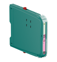
SMART Transmitter Power Supply HiC2027
- 1-channel isolated barrier
- 24 V DC supply (bus powered)
- Input for 2-wire SMART transmitters and current sources
- Signal splitter (1 input and 2 outputs)
- Dual output 0/4 mA ... 20 mA or 0/1 V ... 5 V
- Up to SIL 2 (SC 3) acc. to IEC/EN 61508


Please note: All product-related documents, such as certificates, declarations of conformity, etc., which were issued prior to the conversion under the name Pepperl+Fuchs GmbH or Pepperl+Fuchs AG, also apply to Pepperl+Fuchs SE.
Datasheet excerpt: Technical data of HiC2027
| General specifications | ||
|---|---|---|
| Signal type | Analog input | |
| Functional safety related parameters | ||
| Safety Integrity Level (SIL) | SIL 2 | |
| Systematic capability (SC) | SC 3 | |
| Supply | ||
| Connection | SL1: 1a, 1b(-); 2a, 2b(+) | |
| Rated voltage | 20 ... 30 V DC bus powered via Termination Board | |
| Ripple | within the supply tolerance | |
| Rated current | ≤ 90 mA | |
| Power dissipation | approx. 1.4 W at 20 mA transfer current, 250 Ω in both outputs | |
| Power consumption | 2 W | |
| Input | ||
| Connection side | field side | |
| Connection | SL2: 5a(+), 5b(-): sink SL2: 1a(+), 1b(-), 7a(-): source |
|
| Input signal | 0/4 ... 20 mA | |
| Voltage drop | SL2: 1a(+), 1b(-), 7a(-): ≤ 6.1 V at 20 mA | |
| Short-circuit current | SL2: 5a(+), 5b(-): 25 mA | |
| Input resistance | SL2: 5a(+), 5b(-): max. 500 Ω (BRAIN) (250 Ω load) |
|
| Available voltage | SL2: 5a(+), 5b(-): ≥ 16 V at 20 mA , ≥ 18.5 V at 4 mA | |
| Output | ||
| Connection side | control side | |
| Connection | SL1: 8a(+), 7a(-), channel 1: source and sink SL1: 10a(+), 9a(-), channel 2: source and sink |
|
| Load | channel 1: 0 ... 500 Ω (20 mA)/> 1 MΩ (5 V) channel 2: 0 ... 500 Ω (20 mA)/> 1 MΩ (5 V) |
|
| Output signal | 0/4 ... 20 mA or 0/1 ... 5 V | |
| Ripple | max. 50 µA rms | |
| Transfer characteristics | ||
| Deviation | Iout < 20 µA (0.1 %); Vout < 10 mV (0.2 %) incl. calibration, linearity, hysteresis and fluctuation of supply voltage, at 20 °C (68 °F), 0/4 ... 20 mA, 0/1 ... 5 V | |
| Influence of ambient temperature | current output: 0.25 µA/K voltage output: 80 µV/K |
|
| Frequency range | field side into the control side: bandwidth with 0.5 Vpp signal 0 ... 6 kHz (-3 dB) control side into the field side: bandwidth with 0.5 Vpp signal 0.3 ... 6 kHz (-3 dB) |
|
| Settling time | 6 ms | |
| Rise time/fall time | 2 ms | |
| Galvanic isolation | ||
| Output/power supply | functional insulation, rated insulation voltage 50 V AC | |
| Output/Output | functional insulation, rated insulation voltage 50 V AC | |
| Indicators/settings | ||
| Display elements | LED | |
| Control elements | DIP switch | |
| Factory setting | output: current source | |
| Configuration | via DIP switches | |
| Labeling | space for labeling at the front | |
| Directive conformity | ||
| Electromagnetic compatibility | ||
| Directive 2014/30/EU | EN 61326-1:2013 (industrial locations) | |
| Conformity | ||
| Electromagnetic compatibility | NE 21:2012 EN 61326-3-2:2008 |
|
| Degree of protection | IEC 60529:2001 | |
| Protection against electrical shock | UL 61010-1:2012 | |
| Ambient conditions | ||
| Ambient temperature | -20 ... 60 °C (-4 ... 140 °F) | |
| Mechanical specifications | ||
| Degree of protection | IP20 | |
| Mass | approx. 105 g | |
| Dimensions | 12.5 x 106 x 128 mm (0.5 x 4.2 x 5.1 inch) (W x H x D) | |
| Height | 106 mm | |
| Width | 12.5 mm | |
| Depth | 128 mm | |
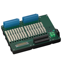
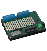
| Mounting | on termination board | |
| Coding | pin 2 and 3 trimmed For further information see system description. |
|
| Data for application in connection with hazardous areas | ||
| EU-type examination certificate | BASEEFA 13 ATEX 0075 X | |
| Marking |  II (1)G [Ex ia Ga] IIC II (1)D [Ex ia Da] IIIC I (M1) [Ex ia Ma] I II (1)G [Ex ia Ga] IIC II (1)D [Ex ia Da] IIIC I (M1) [Ex ia Ma] I |
|
| Input | Ex ia | |
| Supply | ||
| Maximum safe voltage | 250 V (Attention! The rated voltage can be lower.) | |
| Equipment | SL2: 5a(+), 5b(-) | |
| Voltage | 25.2 V | |
| Voltage | 28.2 V | |
| Current | 93 mA | |
| Power | 656 mW | |
| Internal capacitance | 12 nF | |
| Internal inductance | 0 mH | |
| Equipment | SL2: 1a(+), 1b(-), 7a(-) | |
| Voltage | 30 V | |
| Current | 115 mA | |
| Power | 700 mW | |
| Voltage | 5 V | |
| Current | 6.8 mA | |
| Power | 1.6 mW | |
| Internal capacitance | 12 nF | |
| Internal inductance | 0 mH | |
| Output | ||
| Maximum safe voltage | 250 V (Attention! The rated voltage can be lower.) | |
| Certificate | BASEEFA 13 ATEX 0076 X | |
| Marking | II 3G Ex nA IIC T4 Gc |
|
| Galvanic isolation | ||
| Input/Output | safe electrical isolation acc. to IEC/EN 60079-11, voltage peak value 375 V | |
| Input/power supply | safe electrical isolation acc. to IEC/EN 60079-11, voltage peak value 375 V | |
| Directive conformity | ||
| Directive 2014/34/EU | EN IEC 60079-0:2018+AC:2020 , EN 60079-11:2012 , EN 60079-15:2010 | |
| International approvals | ||
| UL approval | E106378 | |
| Control drawing | 116-0349 (cULus) | |
| IECEx approval | ||
| IECEx certificate | IECEx BAS 13.0042X | |
| IECEx marking | [Ex ia Ga] IIC , [Ex ia Da] IIIC , [Ex ia Ma] I | |
| General information | ||
| Supplementary information | Observe the certificates, declarations of conformity, instruction manuals, and manuals where applicable. For information see www.pepperl-fuchs.com. | |
Classifications
| System | Classcode |
|---|---|
| ECLASS 13.0 | 27210119 |
| ECLASS 12.0 | 27210119 |
| ECLASS 11.0 | 27210119 |
| ECLASS 10.0.1 | 27210119 |
| ECLASS 9.0 | 27210119 |
| ECLASS 8.0 | 27210119 |
| ECLASS 5.1 | 27210119 |
| ETIM 9.0 | EC001485 |
| ETIM 8.0 | EC001485 |
| ETIM 7.0 | EC001485 |
| ETIM 6.0 | EC001485 |
| ETIM 5.0 | EC001485 |
| UNSPSC 12.1 | 32101514 |
Details: HiC2027
This isolated barrier is used for intrinsic safety applications.
The device supplies 2-wire transmitters in the hazardous area, and can also be used with current sources.
It transfers the analog input signal to the safe area as two isolated output signals.
Bi-directional communication is supported for SMART transmitters that use current modulation to transmit data and voltage modulation to receive data.
The output is selected as a current source, current sink, or voltage source via switches.
This device mounts on a HiC Termination Board.
Datasheet: HiC2027
| Datasheet | File Type | File Size |
|---|---|---|
| Datasheet HiC2027 | 875 KB | |
| Fiche de données HiC2027 | 1086 KB | |
| Datenblatt HiC2027 | 880 KB | |
| Datasheet HiC2027 | 1157 KB | |
| Hoja de datos HiC2027 | 1089 KB |
Documents: HiC2027
| Manuals | File Type | File Size |
|---|---|---|
| System Manual | 5438 KB | |
| Systemhandbuch | 5450 KB | |
| Instruction leaflets | ||
| Instruction leaflet / Beipackzettel | 138 KB | |
| Instruction manuals | ||
| Инструкции | 169 KB | |
| Instruction manual / Betriebsanleitung | 322 KB | |
| Návod k poużití | 164 KB | |
| Instruktions manual | 163 KB | |
| Instruction manual | 167 KB | |
| Kasutusjuhend | 159 KB | |
| Käyttöohje | 159 KB | |
| Manuel d'instructions | 165 KB | |
| Betriebsanleitung | 170 KB | |
| Οδηγίες χρήσης | 172 KB | |
| Handleiding | 164 KB | |
| Instruction manual / Betriebsanleitung | 162 KB | |
| Használati útmutató | 165 KB | |
| Manuale di istruzioni | 163 KB | |
| Lietošanas pamācība | 162 KB | |
| Instrukciju vadovas | 163 KB | |
| Instrukcja obsługi | 166 KB | |
| Manual de instruções | 164 KB | |
| Manual de utilizare | 163 KB | |
| Návod na poużitie | 163 KB | |
| Navodila za uporabo | 161 KB | |
| Manual de instrucciones | 164 KB | |
| Manual | 160 KB | |
| Documents | ||
| Functional Safety Manual | 1950 KB | |
| Handbuch funktionale Sicherheit | 1961 KB |
CAD+CAE: HiC2027
| CAD | File Type | File Size |
|---|---|---|
| CAD 3-D / CAD 3-D | STP | 2770 KB |
| CAD Portal / CAD Portal | LINK | --- |
Approvals+Certificates: HiC2027
| Certificates | File Type | File Size |
|---|---|---|
| Baseefa ATEX Category (M1) ATEX Category (1) GD | 2118 KB | |
| Baseefa ATEX Category 3 G | 1482 KB | |
| China SITIIAS CCC Ex Certificate | 1332 KB | |
| IECEx Certificate of Conformity | LINK | --- |
| USA Canada UL Hazardous Location Certificate of Compliance cULus UL E106378 | 428 KB | |
| United Kingdom CML UK-Type Examination Certificate UKEX Category (1) D UKEX Category (1) G UKEX Category (M1) | 166 KB | |
| Worldwide exida Functional Safety Assessment | 831 KB | |
| Control Drawings | ||
| Control drawing UL / Control drawing UL | 62 KB | |
| Declaration of Conformity | ||
| EU Declaration of Conformity (P+F) / EU-Konformitäterklärung (P+F) | 54 KB |
Associated Products: HiC2027
| Accessory of | ||||||
|---|---|---|---|---|---|---|
|
||||||
|
||||||


Several hundred products with a SIL/PL assessment, free tools, and brochures in one place: the "Functional Safety Hub" is your starting point when you have to implement safety functions.


Pepperl+Fuchs SE
Lilienthalstraße 200
68307 Mannheim
Germany
info@de.pepperl-fuchs.com
 +49 621 776-0
Pepperl+Fuchs is a leading developer and manufacturer of electronic sensors and components for the global automation market. Continuous innovation, enduring quality, and steady growth have been the foundation of our success for more than 70 years. Pepperl+Fuchs employs 6,300 people worldwide and has manufacturing facilities in Germany, USA, Singapore, Hungary, Indonesia and Vietnam, most of them ISO 9001 certified.